
Commissioning VFD Control Methods: Torque, Speed, and Field Verification
A field-oriented guide to selecting and commissioning V/Hz, sensorless-vector, and closed-loop-vector VFD control without mistaking a running motor for a verified system.
The selected control method determines how effectively a variable-frequency drive estimates or measures motor behavior, especially at low speed. Commissioning must connect that selection to the motor data, driven load, feedback devices, minimum-speed limits, BAS commands, and measured field response.
Technical overview
VFD Control Methods and Torque: field logic map
Control mode changes what the drive knows
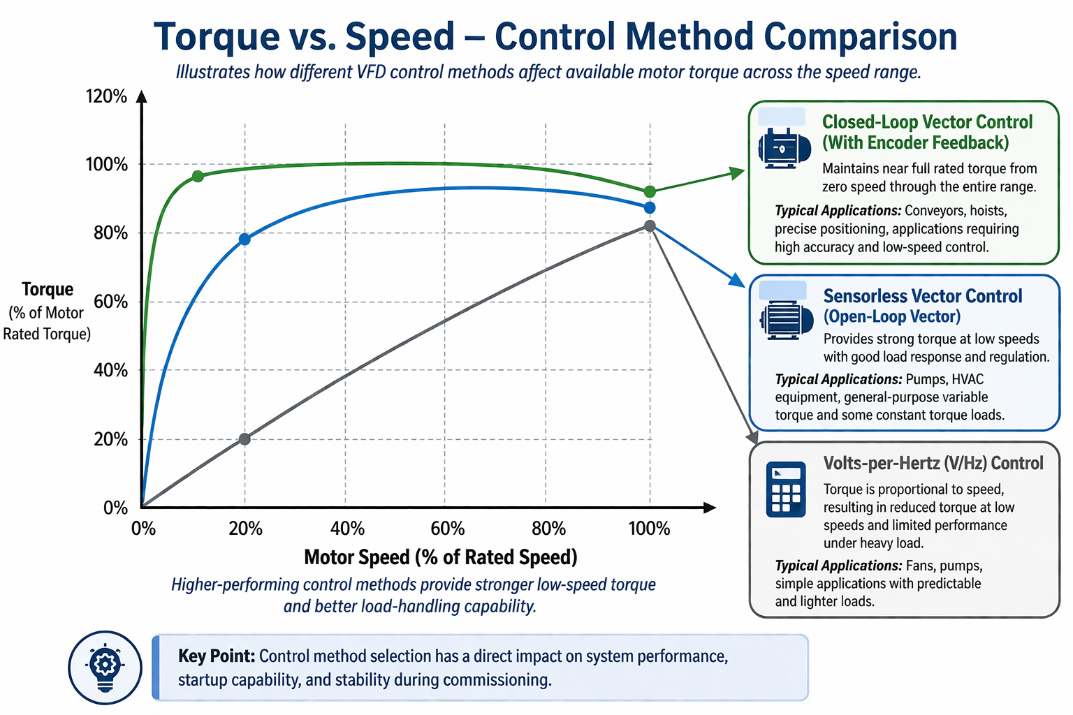
A variable-frequency drive controls motor speed by producing a commanded output frequency and voltage, but the control method determines how much the drive knows about the motor's actual magnetic and mechanical condition. A basic scalar volts-per-hertz mode primarily maintains a programmed voltage-to-frequency relationship. Vector modes use a motor model, measured current, and—in closed-loop applications—encoder feedback to regulate flux and torque more directly.
That distinction becomes most visible during starting, rapid load changes, and low-speed operation. The accompanying graphic is a conceptual comparison, not a guaranteed performance curve. Actual torque, speed range, overload time, minimum frequency, cooling, and regulation depend on the specific drive, motor, tuning, feedback device, carrier frequency, load, and manufacturer limits.
- V/Hz control is often appropriate for stable, predictable fan and pump loads where precise low-speed torque is not required.
- Sensorless-vector control improves low-speed torque and speed regulation by estimating rotor and flux behavior without a shaft encoder.
- Closed-loop-vector control uses encoder feedback when the application requires very low-speed regulation, high starting torque, positioning, holding, or rapid load response.
Select the method from the load—not the menu name
The control mode should be selected from the driven equipment's torque-speed behavior and operating duty. Centrifugal fans and pumps normally have variable-torque loads, while conveyors, positive-displacement pumps, hoists, and many process machines may require constant or high breakaway torque. A drive mode that is satisfactory at normal speed may stall, hunt, overcurrent, or overheat when the system is asked to start loaded or operate continuously near its minimum speed.
The engineer and commissioning provider should confirm the required speed range, starting condition, acceleration time, load inertia, reversing duty, braking, torque limit, speed-regulation accuracy, critical frequencies, and whether the motor's own fan provides adequate cooling at reduced speed. Encoder selection also requires attention to mounting, alignment, pulses per revolution, supply voltage, shielding, direction, and loss-of-feedback response.
- Document normal, minimum, maximum, startup, failure, bypass, and emergency operating conditions.
- Confirm whether the driven equipment can operate safely at every commanded speed and direction.
- Use manufacturer torque-speed and thermal-duty information for the actual motor-drive combination.
Build the parameter set from verified motor data
Vector performance depends on an accurate motor model. Before autotuning or entering parameters, compare the motor nameplate with the approved submittal and the installed drive. Record rated voltage, full-load current, frequency, horsepower or kilowatts, base speed, service factor, efficiency, power factor, pole count when required, and the intended connection. Do not assume that factory defaults represent the installed motor.
Follow the drive manufacturer's procedure for static or rotational autotuning. A rotational tune may require uncoupling the load or establishing a safe condition in which the shaft can turn. Retain the tune method and results. Also record the selected control mode, acceleration and deceleration times, current and torque limits, skip frequencies, minimum and maximum speeds, stopping mode, restart behavior, flying start, sleep or wake logic, carrier frequency, and protective settings.
- Verify local/remote and hand/off/auto behavior before BAS functional testing.
- Confirm the selected speed-reference and start/stop command sources in every intended mode.
- Back up the final parameter file and identify firmware, option cards, communications settings, and restore procedures.
Commission the complete command-and-response path
Begin with installation and pre-start checks: enclosure and ventilation, conductors, grounding and bonding, motor-lead routing, disconnects, overload protection, line and load devices, control wiring, shield terminations, and the absence of prohibited switching on an energized drive output. Confirm phase rotation and driven-equipment rotation using a controlled bump test before sustained operation.
Then test the complete path from the BAS or process command through the drive and motor to the physical system response. At several stable commands, record commanded frequency, actual output frequency, motor speed or feedback, output current, torque indication if available, process flow or pressure, alarms, and status points. Compare independent shaft-speed measurements with drive and BAS values when speed is an acceptance variable.
- Test start, stop, enable, interlocks, safeties, local override, remote reset, and return to automatic operation.
- Prove analog or network speed commands at minimum, intermediate, and maximum values, including scaling and loss-of-signal behavior.
- Verify acceleration, deceleration, coast, ramp, braking, restart, and power-restoration behavior against the approved sequence.
- Challenge high current, overload, feedback loss, communications loss, and other project-required alarm conditions safely.
Prove low-speed performance under a meaningful load
Low-speed verification is where differences among control methods often become operationally important. Test at the lowest approved continuous speed and at any lower intermittent starting or positioning speed. The load must be representative enough to reveal weak torque, unstable estimation, incorrect boost, excessive slip, or inadequate cooling without creating an unsafe condition.
Watch for current that rises without useful shaft response, speed oscillation, audible instability, torque-limit operation, nuisance trips, motor heating, process hunting, or a mismatch between commanded and measured speed. If performance is deficient, do not simply increase boost or current limits. Recheck the control mode, motor data, autotune, feedback, mechanical load, acceleration profile, minimum-speed basis, and manufacturer application guidance.
Document the as-left system, not only the drive display
The final record should connect the selected control mode to the application requirement and the observed system response. Include nameplate data, parameter backup, autotune record, encoder information where applicable, measured test points, alarms, deficiencies, corrections, retests, BAS scaling, trend evidence, and approved minimum and maximum operating limits.
Operator training should cover local and remote control, normal indications, reset restrictions, bypass limitations, loss-of-feedback behavior, common alarms, safe isolation, parameter backup and restoration, and when a repeated drive trip is evidence of a system problem rather than a reason to keep resetting the equipment.
Field application
A practical review checklist
- 01
Confirm the approved motor, drive, load type, control method, duty rating, speed range, torque requirement, and feedback arrangement.
- 02
Inspect enclosure, cooling, conductors, grounding, shielding, motor leads, disconnects, output devices, and control wiring before startup.
- 03
Verify motor nameplate data, connection, parameter entries, autotune method and result, limits, protective functions, and final parameter backup.
- 04
Prove rotation, local/remote control, enable, start, stop, reset, safeties, interlocks, command-source transfer, and return to automatic operation.
- 05
Check speed-command scaling and physical response at minimum, intermediate, and maximum approved speeds using independent measurements where practical.
- 06
Test low-speed torque and regulation under a safe representative load while monitoring current, speed, stability, temperature, and driven-equipment behavior.
- 07
Challenge required alarm and failure responses, including signal loss, communications loss, feedback loss, overload, power interruption, and bypass operation.
- 08
Deliver the as-left parameter file, test data, trends, alarm results, deficiencies, corrections, operating limits, recovery procedure, and operator training record.
Related Free tools
Put the relationships to work.
Authoritative orientation
References and further reading
Use the current adopted or licensed edition applicable to the project. These links provide public orientation and do not reproduce protected standards.
Continue exploring
One article. 235 free engineering calculators.
Move from the concept to a transparent calculation, or return to the complete Insights collection.