
Commissioning at Partial Load: Where the Real Problems Appear
Buildings spend most operating hours away from peak design conditions, where unstable loops, poor turndown, weak staging, and conflicting resets often become visible.
Design-load performance remains important, but part-load testing reveals whether equipment and controls can reduce capacity smoothly, maintain critical minimums, avoid simultaneous operation, and recover as loads change.
Technical overview
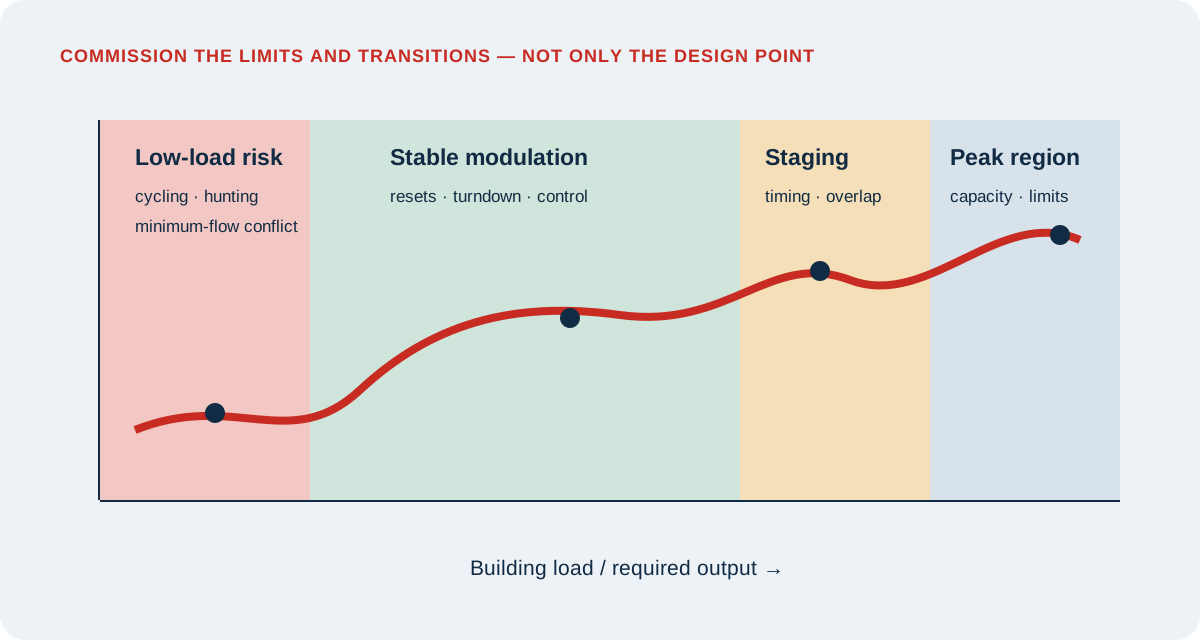
Partial-Load Commissioning: field logic map
Most operating hours are not design days
Mechanical and electrical systems are sized for demanding conditions with appropriate allowances. Actual buildings operate through mornings, mild weather, changing occupancy, solar shifts, equipment diversity, and reduced schedules. A system that performs acceptably at full load may cycle, hunt, overflow, starve, or fight itself during the conditions that dominate annual operation.
Commissioning should therefore define a performance envelope rather than one point. The goal is not to force every possible load artificially. It is to test representative low, intermediate, transition, and high-load conditions and use trends to extend the observation across time.
Turndown belongs to the complete system
A boiler’s burner turndown, chiller’s unloading limit, fan’s minimum speed, pump’s minimum flow, valve’s controllable range, and terminal unit’s minimum airflow interact. The narrowest stable element can define the practical system turndown. Oversized equipment or valves can compress control into a small operating range.
Document minimum stable output, required equipment flows, manufacturer limits, sensor resolution, actuator range, and control deadbands. Compare those values with the lowest credible building load. Where the load falls below the controllable output, the sequence needs an intentional cycling, storage, bypass, or staging strategy.
Resets and staging must work together
Supply-air temperature, duct static pressure, water differential pressure, condenser-water temperature, and plant setpoints are often reset to reduce energy. Independent resets can conflict. Lowering fan pressure may starve a critical zone; raising chilled-water temperature can drive valves open; excessive pump pressure can force valves nearly closed and create hunting.
Functional tests should vary representative load indicators and observe the complete response: setpoint calculation, rate limits, equipment staging, valve or damper positions, critical-zone satisfaction, minimum-flow protection, and return to normal. Acceptance should include stability after the transition.
Look for signatures of weak part-load performance
Useful indicators include rapid cycling, repeated stage changes, persistent overrides, simultaneous heating and cooling, unstable pressure, valves concentrated near closed or open, excessive bypass flow, low chilled-water delta-T, short compressor run time, fan or pump operation above the load requirement, and zones that alternate between opposing modes.
A short snapshot may miss these patterns. Trends should use synchronized intervals and include commands, feedback, setpoints, measured values, equipment status, load indicators, outdoor conditions, alarms, and operating mode. Review both representative days and abnormal periods.
Accept a stable envelope, not a perfect curve
Real buildings contain noise, delays, sensor uncertainty, and discrete equipment stages. Acceptance does not require a mathematically perfect response. It should define acceptable comfort, ventilation, pressure, flow, cycling, energy, and recovery behavior within the approved operating range.
When a system cannot meet the intended envelope, identify whether the cause is sizing, hardware, sensor placement, control logic, tuning, hydraulic or airside distribution, or unrealistic requirements. The correction should be tested across adjacent modes so that improvement at one point does not create a new failure elsewhere.
Field application
A practical review checklist
- 01
Identify minimum stable equipment output, minimum required flow, and approved operating limits.
- 02
Compare system turndown with credible minimum and intermediate building loads.
- 03
Test representative reset inputs, setpoint limits, rate limits, and critical-zone logic.
- 04
Observe equipment staging, anti-cycle timers, lead-lag rotation, and recovery after stage changes.
- 05
Check for simultaneous heating and cooling, overflow, starvation, bypass, and low delta-T.
- 06
Trend commands, feedback, setpoints, loads, weather, status, alarms, and mode together.
- 07
Quantify cycling and instability rather than relying only on visual observation.
- 08
Retest adjacent operating regions after changing sequences or tuning.
Authoritative orientation
References and further reading
Use the current adopted or licensed edition applicable to the project. These links provide public orientation and do not reproduce protected standards.
Continue exploring
One article. 235 free engineering calculators.
Move from the concept to a transparent calculation, or return to the complete Insights collection.