
Failure-Mode Testing: Going Beyond Normal Operating Sequences
Normal operation shows what a system does when everything is available. Failure-mode testing shows whether it detects trouble, protects the facility, and recovers safely.
A resilient building needs defined responses to sensor faults, communication loss, equipment failure, power interruption, and unavailable services. These tests must be risk-assessed, coordinated, and performed without defeating independent protections.
Technical overview
Failure-Mode Testing: field logic map
Reliability is demonstrated when something is unavailable
Many functional tests confirm occupied control under normal inputs and available equipment. Real facilities also experience failed sensors, tripped starters, lost communication, unavailable lead equipment, power interruptions, stuck devices, and invalid operator commands. The sequence should define which failures are detected and how the system responds.
Failure-mode commissioning is not destructive testing. Select safe simulations, establish abort criteria, protect critical operations, coordinate responsible personnel, and preserve independent safeties. Some high-consequence scenarios belong in tabletop exercises or isolated test environments rather than live demonstrations.
Translate each failure into a complete response path
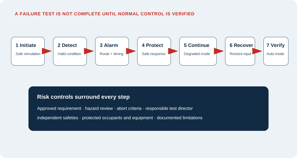
A useful procedure identifies the initiating condition, how it will be simulated, expected detection time, alarm text and priority, equipment response, redundant or degraded operation, operator notification, reset requirements, and automatic restoration. Define what must remain operational and what is permitted to stop.
Test the full path. A controller may identify a failed sensor yet continue using an unsafe default. An alarm may appear locally but never reach the operator. Standby equipment may start but fail to carry the load. Recovery may leave overrides, latched commands, or incorrect lead-lag status.
Use a risk-based hierarchy
Prioritize failures that affect life safety interfaces, mission continuity, freeze protection, pressure control, ventilation, critical temperature, water damage, electrical continuity, plant availability, and costly equipment. Consider credible common causes: shared power, shared network switches, common sensors, common piping, and common software.
For every proposed test, assess personnel safety, equipment risk, occupant impact, process impact, environmental conditions, required permits, and recovery resources. A pretest briefing should assign the test director, controls operator, equipment technician, safety authority, observers, and stop-work responsibility.
Test recovery, not only the alarm
Systems often respond correctly to the initial failure but fail during restoration. Test whether the alarm clears appropriately, normal setpoints return, standby equipment releases or rotates correctly, timers reset, accumulated commands do not cause a surge, and the BAS does not remain in a hidden manual state.
Power restoration deserves particular attention. Confirm controller reboot behavior, time synchronization, schedules, persistent values, network reconnection, equipment restart sequencing, anti-cycle timers, alarms, and safe restoration of local control. Coordinate electrical tests with approved emergency-power procedures.
Record resilience as evidence
The final record should identify the simulated condition, risk controls, actual response, timing, alarms, degraded capability, corrective action, restoration, and remaining limitations. Attach synchronized trends or event logs when they clarify the sequence.
A failure that cannot be safely tested should not disappear from the report. Document the alternative evidence reviewed, the reason live testing was excluded, the residual risk, and the owner’s future verification plan.
Field application
A practical review checklist
- 01
Trace each failure scenario to an approved requirement, sequence, or owner risk decision.
- 02
Select a safe simulation method and document hazards, abort criteria, and restoration steps.
- 03
Brief responsible personnel and identify one test director with stop-work authority.
- 04
Verify detection, alarm wording, priority, routing, timing, and operator instructions.
- 05
Confirm protective action and the capacity of redundant or degraded operation.
- 06
Test restoration, cleared alarms, released overrides, timers, and return to automatic control.
- 07
Capture synchronized trends, event logs, observations, and actual response times.
- 08
Document untested scenarios, alternative evidence, residual risk, and future responsibility.
Authoritative orientation
References and further reading
Use the current adopted or licensed edition applicable to the project. These links provide public orientation and do not reproduce protected standards.
Continue exploring
One article. 235 free engineering calculators.
Move from the concept to a transparent calculation, or return to the complete Insights collection.