
PAM Relays in Building Systems: Small Device, Important Interface
PAM-series relays provide compact, isolated contacts for fire alarm, HVAC, security, lighting, and building automation interfaces—but the exact model and circuit duty matter.
A field-oriented guide to what PAM relays do, how common models differ, where they are used, and how commissioning personnel can verify the complete interface rather than stopping at the relay LED.
Technical overview
PAM Relay Interfaces: field logic map
A compact interface between two circuits
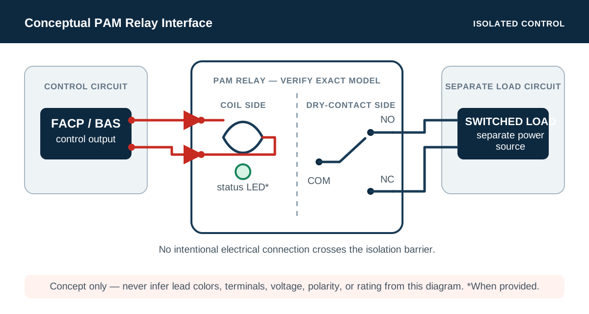
PAM-series relays are encapsulated electromechanical interface devices with flying leads. Applying the specified control voltage energizes an internal coil, which changes the state of a separate contact set. That contact set can open or close a circuit powered from another source without intentionally sharing the control circuit's voltage or reference.
The contacts are commonly described as dry or voltage-free because the relay does not provide voltage through them. The connected source and load determine the switched-circuit voltage and current. In a Form C arrangement, a common lead transfers between normally closed and normally open contacts; a Form A arrangement provides a normally open contact only.
The model number is part of the engineering
Field technicians often use PAM as shorthand for any small potted relay, but the models are not interchangeable. Manufacturer documentation for the Mircom PAM family, for example, identifies different coil-voltage ranges, contact forms, contact ratings, operating currents, and application limitations.
PAM-1 is documented with 10 A Form C contacts and 24 VDC, 24 VAC, or 120 VAC coil options. PAM-2 uses 12 or 24 VDC and 7 A Form C contacts. PAM-3 uses a 9–40 VDC input and a 3 A Form A contact for end-of-line applications, while PAM-4 uses a similar wide-range DC input with 10 A Form C contacts. Product generations and suppliers can differ, so the label and current installation sheet—not field habit—must control the selection and wiring.
- Verify the exact manufacturer, model, date code, and installation document.
- Confirm coil voltage, AC or DC operation, polarity, and continuous-duty limitations.
- Confirm contact form, terminal or lead identification, switched load, and inrush characteristics.
- Confirm the required product listing and suitability for the specific fire alarm or building-system function.
Where PAM relays appear in building systems
The relay solves a common interface problem: one system needs to command or report to another system without directly tying the two circuits together. Typical applications include fire alarm emergency-control interfaces, HVAC shutdown, door and damper functions, equipment enable signals, security interfaces, lighting control, energy-management commands, and dry-contact status feedback.
The relay does not make an interface code-compliant by itself. Circuit supervision, fail-safe behavior, location, enclosure, wiring method, power source, contact rating, sequence, and restoration requirements remain part of the complete design. Fire alarm interfaces in particular must follow the approved design, the exact equipment listings and instructions, the adopted NFPA 70 and NFPA 72 editions, and authority-having-jurisdiction requirements.
Commission the function—not only the relay
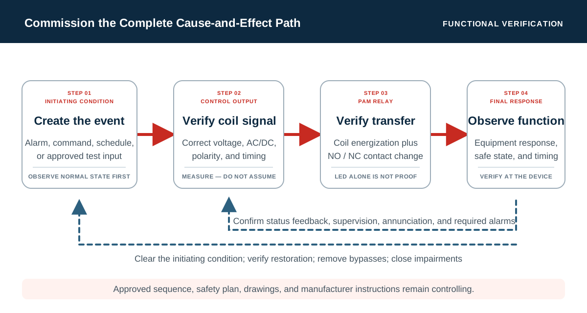
A red LED is useful troubleshooting evidence because it indicates that the relay coil is energized on models equipped with an LED. It does not prove that the contacts transferred, that voltage reached the load, that the controlled equipment responded, or that the initiating and receiving systems recorded the correct state.
A complete functional test begins with the normal condition, creates the approved initiating condition, and observes the entire cause-and-effect path. Confirm control voltage at the coil, contact state before and after energization, voltage or continuity on the switched circuit as appropriate, operation of the final device, annunciation and supervision, required timing, and restoration after the initiating condition clears.
- Trace the initiating signal and the required sequence before testing.
- Verify de-energized and energized contact states against the approved diagram.
- Measure with methods appropriate to the circuit; never assume dry contacts mean an unpowered circuit.
- Test loss of power, broken wiring, or abnormal conditions when required by the approved procedure.
- Document the final controlled response and restoration—not merely a relay click or LED.
Common field problems and practical boundaries
Frequent problems include using the wrong coil lead or voltage, reversing polarity on a protected DC input, confusing normally open and normally closed leads, exceeding a contact rating, switching an inductive load without an approved interface, leaving spare conductors unterminated, locating the relay where it cannot be inspected, and failing to update drawings after a field modification.
Encapsulated construction makes these relays convenient, but it does not eliminate environmental and duty limits. Verify enclosure conditions, temperature, moisture exposure, vibration, conductor protection, separation from other circuits, accessibility, and the manufacturer's continuous-duty guidance. The PAM-1 documentation specifically cautions that extended continuous duty at 120 VAC may not be suitable and directs those applications to another relay family.
Work on fire alarm, life-safety, and energized control circuits should be performed only by qualified personnel under the owner's safety program and an approved test procedure. When a relay participates in an emergency-control function, bypasses and impairments must be controlled, communicated, and restored before the test is closed.
Field application
A practical review checklist
- 01
Record the manufacturer, exact model, coil rating, contact form, contact rating, and applicable installation sheet.
- 02
Trace the normal, alarm, supervisory, trouble, and restoration states on the approved interface diagram.
- 03
Verify coil voltage and polarity, then verify contact continuity or circuit voltage in both relay states.
- 04
Observe the final controlled device and the required status feedback, supervision, annunciation, and timing.
- 05
Confirm mounting, enclosure, conductor protection, spare-lead termination, circuit separation, labeling, and accessibility.
- 06
Remove test bypasses, restore the system, clear impairments, and retain the measured results with the functional test record.
Related Free tools
Put the relationships to work.
Authoritative orientation
References and further reading
Use the current adopted or licensed edition applicable to the project. These links provide public orientation and do not reproduce protected standards.
Continue exploring
One article. 235 free engineering calculators.
Move from the concept to a transparent calculation, or return to the complete Insights collection.